Skip to content

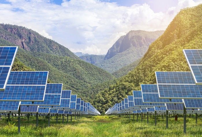
When people think about a solar farm, they picture panels shining in the sun. What they rarely picture is the ground beneath them. Yet the soil and rock under a solar plant carry every load: the weight of the structure, wind uplift and lateral forces, the vibration of tracker motors and the stresses of seasonal swelling and shrinking. They also host the buried cables, the earthing (grounding) system, drainage and access roads.
Poor ground knowledge is a leading cause of cost overruns and delays on solar projects. Piles that cannot be driven because of hard rock, foundations that heave in expansive clay, steelwork that corrodes in aggressive soil, trenches that flood and arrays that suffer washouts after a heavy storm, all trace back to inadequate geological and geotechnical assessment. A well-planned solar site assessment reduces these risks early, when changes are cheap.
This article outlines the geological and geotechnical issues that matter for solar projects, how investigations are carried out and what to ask your consultant, with examples relevant to Kenya’s diverse terrains.
Why Solar Sites Need Geotechnical Investigation
Solar structures look light compared with buildings, but they have particular demands:
- Large number of foundations. A utility-scale solar farm can have tens of thousands of piles or footings. Small savings or errors per foundation multiply across the site.
- Uplift and lateral loads. Wind creates uplift and sideways forces on panels and trackers, which are often more critical than the weight of the structure.
- Tolerances. Trackers and fixed-tilt structures need alignment tolerances, so differential settlement or heave can reduce performance or damage components.
- Long life. Plants are designed for 25 to 35 years, so soil behaviour over decades matters, including corrosion and seasonal moisture changes.
- Vast footprint. The geology can change across a site, so a few boreholes in one corner are not enough.
- Interaction with other systems. Soil thermal resistivity affects cable sizing, and electrical resistivity affects earthing design.
Investigation should therefore be tailored to the project, scaled to its size and the variability of the ground.
Step 1: Desktop Study and Geological Screening
Before any field work, geologists review:
- Geological maps and reports, identifying rock types, faults, volcanic or sedimentary units and known geohazards.
- Topography and drainage from DEMs, satellite imagery and drone surveys. See our articles on topographic maps and GIS.
- Soil maps and land use.
- Flood and rainfall information, including historical events.
- Existing borehole and well records, which give information on depth to bedrock and groundwater.
- Seismic hazard information. The Rift Valley is tectonically active, so consider active faults and ground shaking.
- Neighbouring projects and local construction experience.
- Access, environmental constraints and land tenure.
This stage identifies the main ground risks and helps to design the field investigation. It can also flag fatal flaws, such as active fault traces, flood-prone land or protected areas, before large sums are spent.
Step 2: Field Investigation Methods
A typical solar geotechnical investigation includes several complementary tools:
1. Trial pits and test pits. Excavated with a backhoe to depths of 2 to 4 metres, they allow geologists to observe soil layers directly, estimate depth to rock, check for expansive clays and cemented layers, observe groundwater seepage and collect samples. Pits are a cost-effective way to cover a large area.
2. Boreholes and in-situ tests. Drilled boreholes provide deeper information and allow tests such as the Standard Penetration Test (SPT) to estimate soil strength, and sampling for laboratory tests. Rock coring may be needed where bedrock is shallow. For large sites, boreholes are placed on a grid or at representative locations, with more in variable areas.
3. Dynamic cone penetrometer (DCP) and cone penetration tests (CPT). Quick, economical ways to profile soil strength with depth across many locations, useful for mapping variability and for preliminary pile design.
4. Pile load tests (pull-out, compression and lateral tests). These are the most important tests for solar foundations. Trial piles of the planned type are installed at selected locations and loaded to measure uplift (pull-out) capacity, lateral capacity and compression capacity. Results allow engineers to select pile type and embedment depth with confidence, to optimise the design, and to estimate installation difficulty (refusal rates). Tests are done on trial areas representing the different soil zones.
5. Geophysical surveys.
- Electrical resistivity surveys (such as Wenner arrays) measure soil resistivity for earthing design and also help map changes in soil and depth to bedrock.
- Seismic refraction or MASW (multichannel analysis of surface waves) estimate depth to bedrock and rock rippability, useful for planning excavation and pile driving.
- Ground-penetrating radar for shallow features such as buried utilities and voids. See our articles on geophysics for groundwater and VES, since the same methods apply to near-surface ground characterisation.
6. Groundwater assessment. Depth to groundwater and seasonal fluctuation affect foundation design, corrosion, trench stability and flood risk. Piezometers or observation holes may be installed on large or wet sites.
7. Laboratory testing. Samples are tested for particle size, plasticity (Atterberg limits), moisture content, swelling potential, compaction, California Bearing Ratio (CBR) for roads, shear strength, and chemical properties that control corrosion: pH, chlorides, sulphates and soil resistivity. Thermal resistivity tests support cable design.
8. Site walkover and mapping. A geologist or engineer inspects the site for outcrops, erosion, drainage lines, cracks, springs, signs of instability, previous land use and fill.
Key Geological and Geotechnical Issues for Solar Sites
1. Foundation type and pile embedment. Common solar foundation types are:
- Driven steel piles: the most common for large plants where soil permits, quick to install and economical.
- Ground screws and helical piles: suited to soft or variable ground and to sites where driving is difficult, and removable, which is attractive for temporary or leased land.
- Concrete ballasted foundations: blocks resting on the surface or shallow footings, used where piling is not feasible, such as shallow rock, landfills or sensitive sites, though they use more materials.
- Drilled and grouted piles or rock anchors: for shallow bedrock or very hard ground. The investigation should show which methods are feasible, their expected capacity and installation challenges, and how much variation to expect across the site.
2. Shallow rock and hard layers. In volcanic terrains, such as parts of the Rift Valley and highlands, lava flows, cemented layers or boulders can stop pile driving (pile refusal). Where bedrock is shallow, pre-drilling, rock anchors or ballasted systems may be needed, increasing cost and time. Early knowledge of refusal depth allows proper budgeting. Seismic refraction and trial pile driving help map this.
3. Expansive soils (black cotton soils). Large areas of Kenya, including parts of the Rift Valley, the Lake Victoria basin, the Athi plains and coastal and northern areas, are covered by expansive clays, commonly known as black cotton soils. These swell when wet and shrink when dry, producing ground movement that can lift foundations, tilt structures and crack roads. The movement is typically concentrated in the upper few metres, the active zone. Piles should extend below the active zone into stable ground, and can be designed to resist uplift from swelling (skin friction and uplift forces). Surface drainage and road design also require care. Laboratory tests for plasticity and swell help to identify this issue. See our article on foundation design in expansive soils.
4. Soft or loose soils and collapsible soils. Loose sands, soft clays or collapsible soils can have low capacity. Compaction, deeper piles, ground improvement or alternative foundation types may be necessary.
5. Corrosivity. Buried steel piles and earthing components corrode in aggressive soils. Corrosion depends on soil resistivity, pH, chloride and sulphate content, moisture and oxygen availability. Saline soils, such as those in arid and semi-arid areas and near the coast, can be highly corrosive. Mitigation includes galvanising or heavier coatings, thicker steel sections (a corrosion allowance), protective measures and careful material selection, informed by laboratory tests. Concrete may need sulphate-resistant cement in sulphate-rich soils.
6. Earthing and soil resistivity. A low-resistance earth system is critical for safety and lightning protection. Soil resistivity varies with soil type, moisture and temperature. Dry, rocky or sandy soils have high resistivity and may need extensive earthing electrodes, soil enhancement or deeper rods. Surveys using resistivity arrays across the site give the data to design the system. Seasonal variations should be considered, since resistivity is higher in the dry season.
7. Thermal resistivity of soils for cables. Buried cables heat up, and the surrounding soil’s ability to dissipate heat affects cable rating. Dry sandy soils have high thermal resistivity, so the cables may need bigger cross-sections or special backfill.
8. Drainage, flooding and erosion. Heavy rainfall in Kenya’s tropical climate can cause flash floods and erosion, especially on slopes and in seasonal river valleys. Poor drainage can scour foundations, wash out roads and trenches and damage equipment. Assessment should include hydrology and flood modelling, drainage design, erosion control and avoiding flood channels, floodplains and low-lying areas. Slope stability should be checked on hilly sites, and cut and fill should be minimised.
9. Groundwater and moisture. High groundwater can affect pile installation, excavation stability, corrosion and concrete. In arid regions, groundwater may be deep, but seasonal flooding can still occur. Conversely, deep groundwater is relevant for boreholes supplying water for panel cleaning and construction.
10. Seismic and fault hazards. In seismically active regions such as the Rift Valley, ground shaking and, near active faults, surface rupture are real considerations. Avoid building directly on active fault traces, and design structures with appropriate seismic provisions. Volcanic hazards, such as lava flows, ash fall and ground cracks (fissures), also exist in some rift areas. A geological hazard assessment should consider these.
11. Slope stability and landslide risk. On sloping sites, assess the stability of natural slopes and cuts, and the risk of landslides, creep and erosion. Panel arrays on slopes need stable ground, careful drainage and often terracing.
12. Karst, voids and mine workings. In limestone areas, there can be cavities and sinkholes. Historic mining or quarrying may leave voids and unstable ground. Geophysics and mapping help to detect these.
13. Landfill and fill ground. Solar projects are sometimes built on former landfills or fill areas, where settlement and gas generation require special attention.
14. Aggregate and material sources. Roads, hardstands and concrete need aggregates. Identifying local borrow pits and quarries and testing the materials can cut costs.
15. Water for construction and operation. Construction needs water for dust control and concrete, and operation may need water for panel cleaning, particularly in dusty regions. Boreholes may supply this. Hydrogeological assessment ensures that groundwater is available and sustainably used, and compliance with abstraction permits is required. See our articles on hydrogeological surveys and permits.
Putting the Data Together: Zoning and Design
The results are compiled into a geotechnical report and ground model that typically includes:
- Site geology and soil profile descriptions with a map of ground zones.
- Test results and interpretation.
- Foundation recommendations, including pile types, embedment depths, capacities, installation methods and expected refusal areas.
- Corrosion assessment and protection recommendations.
- Earthing and thermal resistivity data.
- Drainage, flood and erosion recommendations.
- Earthworks and road design guidance, including CBR values.
- Geohazard assessment and mitigation measures.
- Construction considerations, such as dewatering, rippability and seasonal constraints.
- Risks and uncertainties, and recommendations for further investigation.
GIS is a valuable tool for integrating the data, mapping ground conditions across the site and optimising layout, for instance by placing arrays on the best ground and keeping roads out of flood paths. See our GIS articles.
How Much Investigation Is Enough?
There is no universal rule, but practical guidance includes:
- Scale investigation to the project size and ground variability. A small rooftop or ground array may need only a few pits, while a utility-scale plant needs systematic coverage.
- Use phased investigation. Start with desktop study and reconnaissance, then targeted tests and finally trial piling.
- Increase density where conditions vary or risk is high.
- Account for seasonal effects. Soil moisture and groundwater vary, and expansive soils behave differently in wet and dry seasons.
- Check the budget logic. Investigation typically costs a small fraction of the project cost, while unforeseen ground conditions can add substantially more. Investing early usually saves money.
Common Mistakes
- Relying on a handful of tests for a large, variable site.
- Skipping pile load tests and discovering poor pull-out capacity or refusal during construction.
- Ignoring black cotton soils, or assuming that standard foundations will work.
- Overlooking corrosion and using standard coatings in aggressive soils.
- Underestimating flood and erosion risk, and building in drainage lines.
- Not testing soil resistivity, then discovering that earthing targets cannot be met.
- Choosing a site without checking faults, slope stability or geohazards.
- Failing to plan water supply for construction and cleaning.
- Treating the geotechnical report as a box-ticking exercise rather than a design input.
Regional Considerations in Kenya
Rift Valley floor and lake basins. Lacustrine sediments, volcanic ash and expansive clays are common. Salinity may promote corrosion, flood risk can be high near lakes and seismic and volcanic hazards must be considered.
Highlands and volcanic terrain (central Kenya). Variable soils over lavas and tuffs, shallow rock in places, and slopes, requiring pile refusal assessment and drainage design.
Arid and semi-arid north and east. Sandy and gravelly soils, shallow calcrete or hardpan layers, high soil resistivity, flash floods in seasonal rivers and saline soils. Water for construction and cleaning can be scarce and expensive.
Coastal areas. Corrosive, saline soils and groundwater, possible flooding and soft deposits, and sulphate-bearing soils.
Basement terrains (Machakos, Kitui and others). Residual soils over weathered rock, with variable depth to bedrock and hard rock in places.
Western Kenya. Lateritic and clay soils, high rainfall, drainage and erosion issues.
Local geological knowledge helps anticipate these differences and design appropriate investigation programmes.
Frequently Asked Questions
Do small solar projects need a geotechnical study? Even small ground-mounted systems benefit from basic checks, such as trial pits and a review of soil type. Large projects require comprehensive investigation.
What is a pile pull-out test? A trial pile is installed and pulled upward with a controlled load to measure how much uplift force the soil can resist. It is key for wind uplift design.
Why does black cotton soil matter? Its swelling and shrinking can lift or tilt foundations and damage roads. Foundations should be designed to cope with it.
How long does a geotechnical investigation take? From days for small sites to several weeks for large ones, including laboratory testing and reporting.
Can I use a standard foundation design from another project? Not safely. Each site’s ground conditions are unique, and standard designs should be checked against site-specific data.
Who should carry out the investigation? A qualified geotechnical engineer or engineering geologist with experience in the local ground conditions and solar projects.
Conclusion
A solar project is only as good as the ground it stands on. A thorough site assessment combines desk study, field investigation, laboratory testing and engineering interpretation to identify the right foundation types, manage expansive soils, corrosion, drainage and hazards, and optimise layout and cost. Investing in geological and geotechnical understanding early reduces risk and helps deliver a plant that performs for decades.
For geological, geotechnical, hydrogeological and GIS input into solar and other energy projects, contact Reg. Geol. Mbugua Githae (MGSK) through consult.innercoregeoconsultants.co.ke.