Skip to content

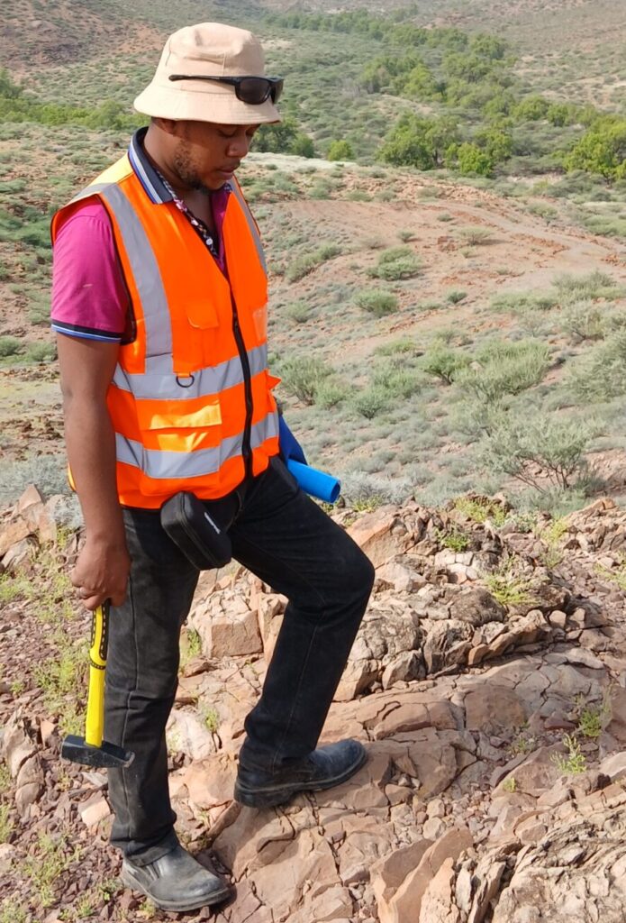
A good structural field kit is simple: a compass-clinometer (such as a Brunton or Silva type), a GPS or mapping app, a hand lens, a hammer, a notebook or tablet, a camera, a marker for photographing scale, and a protractor or stereonet template. Digital apps such as FieldMove Clino or similar tools speed up data capture, but keep a paper backup.
Good habits matter more than gadgets. Record the location, date, rock type, and orientation of every structure measured. Use a consistent convention, such as dip direction / dip (for example, 120/45) or strike/dip with right-hand rule, and state which you use. Take multiple measurements across an outcrop, because single readings can mislead. Always photograph the structure with a scale.
Part One: Faults
What is a fault? A fault is a fracture in rock along which the two sides have moved relative to each other. The movement can be millimetres or hundreds of kilometres. Faults are classified by the relative movement.
Normal faults. The hanging wall (the block above the fault plane) moves down relative to the footwall. They form in extension and are the dominant structures of the East African Rift, producing the great escarpments of the Kenya Rift.
Reverse and thrust faults. The hanging wall moves up relative to the footwall. Reverse faults dip steeply, and thrust faults dip gently. They form in compression and are common in the Mozambique Belt and Archean greenstone belts.
Strike-slip faults. Blocks move horizontally past each other. If an observer standing on one side sees the opposite side move to the right, the fault is dextral (right-lateral); if to the left, sinistral (left-lateral).
Oblique-slip faults combine dip-slip and strike-slip components.
Field indicators of faults.
- Offset markers: a bed, dyke, vein, or contact displaced across a fracture.
- Slickensides and slickenlines: polished, grooved surfaces on the fault plane. The grooves (slickenlines) show the direction of slip, and small steps (slickenfibres) can show the sense.
- Fault gouge and breccia: powdery clay-rich gouge or fragmental breccia along the fault.
- Drag folds: layers bent near a fault in the direction of movement.
- Fault scarps: steps in the landscape created by recent movement, common in the Rift.
- Juxtaposition of unlike rocks: older rocks against younger ones, or abrupt changes in rock type or metamorphic grade.
- Springs and linear vegetation: lines of springs, wet ground, or distinct vegetation can follow faults.
- Silicification or alteration: hydrothermal fluids often use faults, leaving quartz veins or altered rock.
What to measure. Record the strike and dip of the fault plane, the orientation (plunge and trend) of slickenlines, the sense of movement, the width of the damage zone, and any associated veins or fractures. Estimate displacement if marker beds allow.
Part Two: Folds
What is a fold? A fold is a bend in layered rock, formed when the rock is shortened or sheared. Folding records how the crust responded to compression or shear.
Basic terms. The hinge is the line of maximum curvature, and the limbs are the flanks on either side. The axial plane is the imaginary surface that divides the fold into two halves, containing the hinge lines of successive layers. The plunge of a fold is the inclination of its hinge line.
Types of folds. An anticline is an arch-like fold with older rocks in the core. A syncline is a trough-like fold with younger rocks in the core. Antiforms and synforms describe the shape when the age order is unknown. Folds may be open, tight, or isoclinal depending on how closely the limbs are squeezed. They may be upright, inclined, overturned, or recumbent depending on the axial plane’s orientation. Parasitic folds are small folds on the limbs of larger folds, and their asymmetry (S, Z, or M shapes) helps locate the larger fold hinge.
Field indicators of folds.
- Changing dip direction of bedding or foliation across an area.
- Repeated sequences of rock units on either side of a hinge.
- Younging directions from sedimentary structures such as graded bedding, cross-bedding, and ripple marks, used to determine whether layers are upright or overturned.
- Axial planar cleavage or foliation parallel to the axial plane.
- Minor folds and crenulations on outcrop surfaces.
- Map patterns: curved outcrop patterns and closures at fold noses.
What to measure. Collect numerous bedding or foliation measurements across the fold, then plot them on a stereonet to determine the fold axis (as the intersection of the best-fit great circle with the poles). Measure the axial plane, hinge plunge and trend, interlimb angle, and fold style. Note whether multiple fold generations are present, since refolding can produce complex interference patterns.
Part Three: Lineaments
What is a lineament? In the original usage, a lineament is a mappable, linear or slightly curved feature on the Earth’s surface that differs from adjacent patterns and is presumed to reflect subsurface geology. Lineaments are most commonly identified on satellite images, aerial photographs, digital elevation models, and geophysical maps. They may represent faults, joints, dykes, shear zones, lithological contacts, or fracture corridors.
Why they matter. Lineaments can reveal regional structural trends, guide exploration for minerals, geothermal fluids, and groundwater, and highlight engineering hazards. In the Rift Valley, lineaments follow fault systems and volcanic alignments, while in basement terrains they may mark shear zones and fracture corridors.
Cautions. Not every straight line is geological. Roads, railways, fences, power lines, field boundaries, and river channels can all produce linear features. Illumination bias is another trap: features perpendicular to the sun direction in an image appear more prominent, while those parallel to it fade. Use multiple illumination azimuths on hillshade images to avoid bias.
Validating lineaments. Always confirm with field evidence, geological maps, geophysical data, or boreholes. Record whether a lineament corresponds to an observed fault, joint set, or dyke. Where validation is not possible, classify lineaments as “interpreted” rather than “mapped.”
Distinguishing Faults from Joints
A common beginner question is how to tell a fault from a joint. A joint is a fracture along which no visible displacement has occurred. A fault shows displacement, even if small. Look for offset markers, slickensides, or gouge. Joints often occur in parallel sets with regular spacing, while faults are fewer and may be accompanied by damage zones. Joint sets can still be important: they control rock mass strength, groundwater flow, and the orientation of veins.
Distinguishing Folds from Tilted Blocks
Tilted layers alone do not prove folding. If dips are uniform over a wide area, the rocks may simply be tilted, perhaps by faulting or regional uplift. A fold needs a change in dip direction across a hinge, which produces a repeating pattern when traversed. Always collect bedding data on both sides of a suspected fold.
Structures of the East African Rift
The Kenya Rift illustrates faults and lineaments on a grand scale. Large border faults form steep escarpments such as the Elgeyo, Nguruman, and Mau scarps, while smaller rift-floor faults break the valley floor into narrow grabens and horsts, producing the dense fault swarms visible in areas such as the Kenya Rift near Naivasha and the Magadi region. Volcanic centres, such as Longonot, Suswa, Menengai, and Olkaria, align along fault zones and fissures. Many faults and lineaments follow older basement structures, such as the Proterozoic shear zones of the Mozambique Belt, which were reactivated during rifting. In Archean terrains of western Kenya, folded greenstone belts and shear zones show a different, older deformation style.
Recording and Presenting Your Observations
Good field data need to be organised. Use a standard field sheet or app form for each station, with fields for location, rock type, structure type, orientation, kinematic indicators, and notes. Sketch outcrops with annotations, and take photographs with scale. Back at base, plot measurements on stereonets, draw structural maps with standard symbols, and construct cross-sections. Keep data in a GIS so that it can be combined with other layers.
Common Mistakes
Typical mistakes include confusing bedding with foliation, mixing measurement conventions, measuring only weathered surfaces, using the compass near magnetic rocks or metal objects (which causes errors, particularly in iron-rich rocks), ignoring magnetic declination, failing to distinguish between fault planes and joint planes, and assuming that one structural episode explains everything. Always cross-check measurements and keep notes on uncertainty.
Frequently Asked Questions
Do I need to know the age of a structure? Relative age, from crosscutting relationships, is often enough for mapping and exploration. Absolute ages require geochronology.
What is the best way to learn? Practise on outcrops, compare with published maps, and discuss interpretations with experienced colleagues.
How accurate must measurements be? A few degrees of uncertainty is typical in the field, but systematic errors such as declination must be corrected.
Conclusion
Faults, folds, and lineaments form the vocabulary of structural geology. Learning to recognise them in the field, measure them carefully, and validate remote sensing interpretations turns scattered observations into a coherent structural picture. Whether you are exploring for gold in a greenstone belt, mapping fault hazards in the Rift Valley, or siting a borehole in fractured basement, these skills form the foundation of sound geological work in Kenya and beyond.