Skip to content

Electrical resistivity is one of the most widely applied geophysical methods in Kenya. It is relatively affordable, portable, and highly effective for groundwater exploration, geotechnical investigation, and some mineral and environmental applications. Understanding how it works helps clients interpret results and make better decisions.
The Basic Principle
Different earth materials resist the flow of electric current to different degrees. In a resistivity survey, current is injected into the ground through two electrodes, and the resulting voltage difference is measured between two other electrodes. From the current, voltage, and electrode geometry, the apparent resistivity is calculated. Measuring at different electrode spacings or positions reveals how resistivity varies with depth and distance.
Resistivity is expressed in ohm-metres (Ωm). Its value depends on:
- Rock or soil type: Clay and saline sediments conduct well (low resistivity), while dry crystalline rock and dry gravel resist current (high resistivity).
- Porosity and fracturing: More void space generally allows more water, lowering resistivity.
- Water saturation: Wet materials conduct better than dry ones.
- Water salinity: Saline groundwater produces very low resistivity.
- Temperature and clay content: Both can influence readings.
Vertical Electrical Sounding (VES)
VES, often using the Schlumberger array, expands the electrode spacing progressively about a fixed centre point. As spacing increases, current penetrates deeper, and the resulting curve is interpreted to produce a one-dimensional model of layers: thickness and resistivity for each layer. VES is cost-effective and well suited for layered geology, such as sediments and weathered basement.
Its limitation is that it assumes horizontal layering and gives information at a single point. In complex geology with steep structures or lateral variation, VES can mislead if used alone.
Electrical Resistivity Tomography (ERT)
ERT uses many electrodes laid out along a line, with automated switching to collect hundreds of measurements at different spacings and positions. Inversion software converts these data into a two-dimensional resistivity section. ERT shows lateral changes clearly, so it is much better at imaging fractures, faults, karst voids, buried channels, and contamination plumes. Three-dimensional surveys are also possible by using several parallel lines.
Common Electrode Arrays
- Schlumberger: Good for depth sounding with efficient field operation.
- Wenner: Strong signal and good vertical resolution, commonly used in profiling.
- Dipole-dipole: Better lateral resolution, useful for steep structures and fractures.
- Pole-dipole and pole-pole: Used where deeper penetration or logistical constraints exist.
The choice depends on target geometry, depth, noise, and available space.
Main Applications
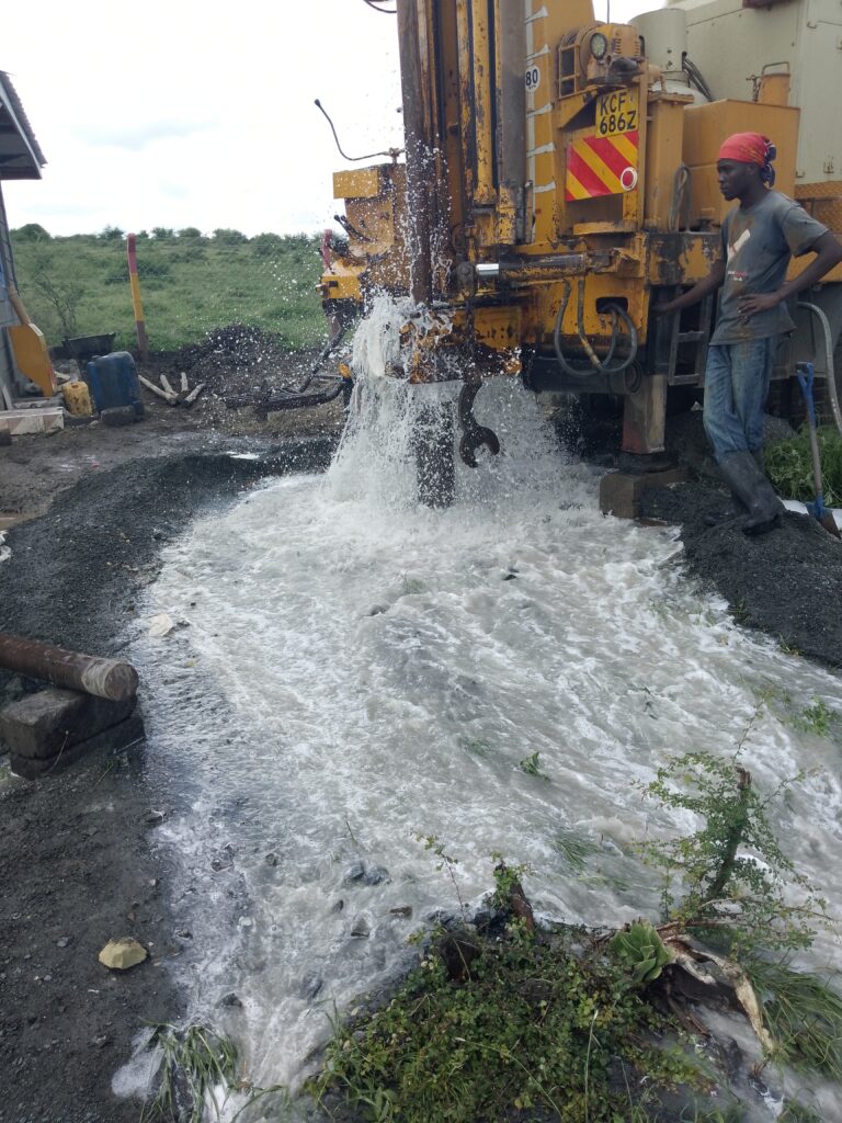
Groundwater exploration. Resistivity helps identify weathered zones, fractures, sand and gravel aquifers, and the depth to bedrock. In basement terrains, low-resistivity vertical zones can indicate fracture zones with water, making them priority drilling targets.
Aquifer characterisation. Resistivity distinguishes clay from sand, and fresh from saline water, supporting aquifer mapping and salinity assessment.
Geotechnical investigation. Surveys estimate depth to bedrock, detect weak or water-saturated zones, and locate buried channels or cavities beneath proposed structures.
Mineral exploration. Resistivity is combined with induced polarisation to map silicification, sulphide-bearing zones, and veins.
Environmental studies. It helps trace leachate plumes, saline intrusion, and contaminated groundwater.
Dam and infrastructure siting. It maps seepage paths and foundation conditions.
Field Procedure
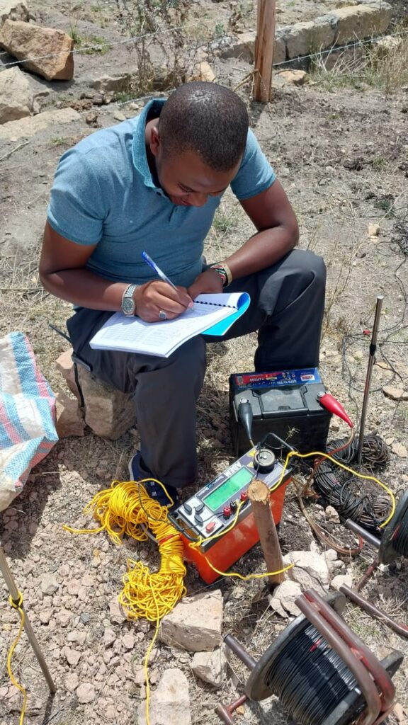
A typical field day begins with survey design and line layout using GPS. Electrodes are installed, and contact resistance is checked and improved if necessary by wetting the soil or adding electrodes. Data are collected and viewed in the field for quality checks. Noisy or inconsistent readings are repeated. Notes on surface conditions, geology, nearby infrastructure, and recent rainfall are recorded, since these factors affect interpretation.
Interpreting Results Responsibly
Resistivity values have no universal meaning. A value of 50 Ωm might indicate saturated fractured rock in one place and clay-rich soil in another. Reliable interpretation requires:
- Calibration with geology and existing boreholes.
- Awareness of equivalence, where different layer combinations can produce similar curves.
- Awareness of noise from power lines, fences, and pipelines.
- Integration with other methods, such as magnetics or EM.
Reports should present uncertainty and avoid overpromising yield from resistivity alone, because yield also depends on aquifer storage and recharge.
Limitations
- Depth of investigation is limited by electrode spacing and available space.
- Resolution decreases with depth.
- Very dry or rocky ground makes electrical contact difficult.
- Urban and industrial noise can degrade data quality.
- Results do not directly measure water quantity or quality.
Best Practice Tips for Clients
- Prepare access to the site and clear line paths in advance.
- Share information about existing boreholes, wells, buried pipes, and cables.
- Plan surveys with enough lines to represent the target area.
- Request both raw data and interpreted sections.
- Combine resistivity with geological assessment for borehole siting.
Conclusion
Electrical resistivity surveys offer an efficient, scientifically grounded way to understand what lies beneath the surface. When properly designed and interpreted, they improve the success of water, engineering, and exploration projects in Kenya.
Innercore Geoconsultants Services Limited conducts VES and ERT surveys with expert interpretation tailored to your project. Contact us to plan your resistivity survey.